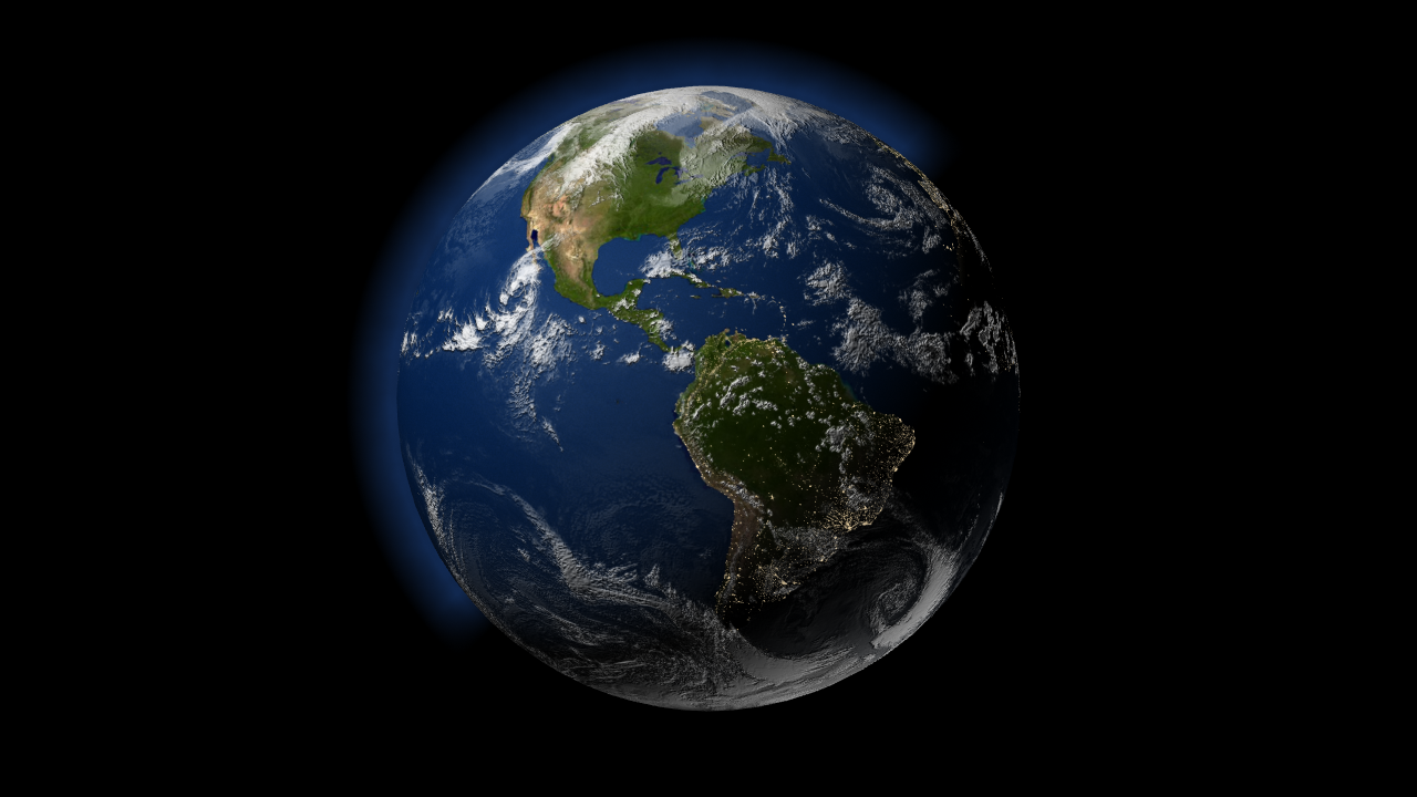
In this series of tutorials, I will show how I modeled and textured the Earth in the image above using LightWave 3D. The surfaces are primarily driven by image maps along with some custom logic in the Node Editor.
You can download the images I used in my model in this zip file. The images are collected from a few online resources: Planet Pixel Emporium provided most of the images, and NASA helped with some others.
Create the Model
In Modeler:
- Create a new ball:
- Type: Tesselation
- Segments: 4
- Center X,Y,Z: 0,0,0
- Radius X,Y,Z: 1m, 1m, 1m
- Press the tab key to convert the polygons to subpatches.
- Press ‘q’ to assign a surface to the object. Name the new surface “Earth”.
- On the second layer, create a new ball:
- Type: Tesselation
- Segments: 4
- Center X,Y,Z: 0,0,0
- Radius X,Y,Z: 1.2m, 1.2m, 1.2m
- Press the tab key to convert the polygons to subpatches.
- Press ‘q’ to assign a surface to the object. Name the new surface “Atmosphere”.
- Press ‘h’ to use the scale tool. In the ‘Top’ view, scale the sphere in the Z direction to 0%.
- Name the first layer “Earth” and the second layer “Atmosphere”. The second layer should have the first layer as its parent.
- Save the object as “Earth”.
Setup the Basic Scene
- Create a new, empty scene in Layout.
- Load the “Earth” object.
- Edit your camera to have the following settings:
- Lens Focal Length: 120mm
- Antialiasing: 5
- Position X,Y,Z: 0, 0, -20m
- Rotation: 0, 0, 0
- Open the light properties and change the “Ambient Intensity” to 0%.
- Press F5 to open the Surface Editor. Choose the “Earth” surface. Make sure the “Smoothing” checkbox is enabled for the surface.
- Most of the texturing will be done in the Node Editor. However, I found that the OpenGL viewports only display the textures that are directly assigned to the object in the main Surface Editor tab, so let’s assign some textures that will show up in the viewports. Assign a texture to the “Color” channel of the surface and use “Image Type”:
- Projection: Spherical
- Image: earth_map.jpg
- Texture Axis: Y
- Assuming your options are set correctly in Layout, you should now see the map of the world in any viewport that is set to “Textured”. Let’s rotate the globe so that we see North America. Set the “Earth:Earth” object’s rotation heading to -75 degrees.
- The “Earth:Atmosphere” object will be used later. For now, open the Scene Editor and uncheck that object so it does not render.
Surface the Earth Land
- In the “Earth” surface editor, make sure the checkbox next to the “Edit Nodes” button is enabled. Press “Edit Nodes” to launch the Node Editor.
- Create a new Image node (2D Textures->Image). Select the node and press ‘r’, then rename it to “LandColor”.
- Double-click LandColor and set the image properties:
- Image: earth_map.jpg
- Mapping: Spherical
- Axis: Y
- Close the properties, then click on LandColor to make sure it is selected. Press control-c, then control-v to copy/paste a clone. Click the new node and press ‘r’ to rename it to ‘LandBump’.
- Double-click LandBump and change the “Image” value to to earth_greyscale_elevation_8k.jpg. Set the “Bump” to 1100%.
- Create a new Standard material node (“Materials->Standard”). Rename the node to “LandMaterial”.
- Connect the “color” output from LandColor to the “color” input of LandMaterial.
- Connect the “bump” output from LandBump to the “bump” input of LandMaterial.
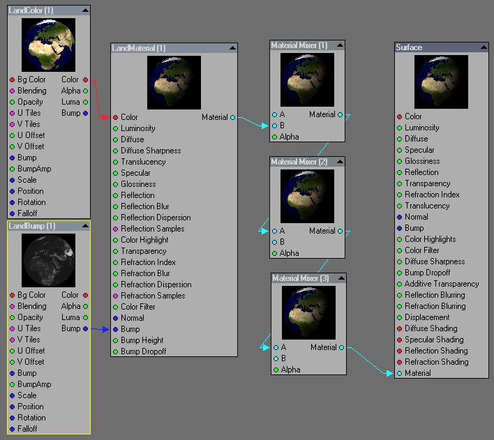
- Create three Material Mixer nodes (Materials->Material Mixer). Place them in a vertical line, with the “Material Mixer (1)” at the top (see screenshot). These will mix all the future materials we create for the various layers of the total surface.
- Connect the “Material” output of LandMaterial to the “B” input of “Material Mixer (1)’.
- Connect “Material Mixer (1)” output to “Material Mixer (2)” input “A”.
- Connect “Material Mixer (2)” output to “Material Mixer (3)” input “A”.
- Connect “Material Mixer (3)” output to the “Material” input of the “Surface” node.
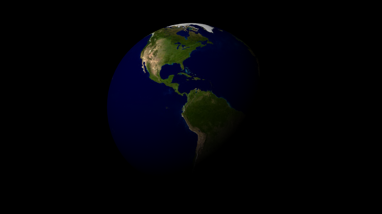
- Finally, set the “Alpha” of “Material Mixer (1)” to 100% (double-click on the node to set a static value for the Alpha). The preview thumbnail of the “Surface” node should show the earth texture. If you render the scene, you should see the Americas along with some bump detail.
Before moving on to the next section, you can reduce the clutter of the node network by minimizing the land images and material nodes, so they take up less room.
Continue reading Part 2 of the tutorial!